Quarantine Logs 2020-04-13: Circuit-Sim Progress!
Been a week! This is by far the most frequently I’ve ever posted. I’m hoping to keep it up.
I’m happy to update that I made a little progress on the circuit simulator I’ve been working on. Here I’ll get into some of what that’s all about in a little bit more detail. All the relevant code is up on Github, though it’s really bare-bones and without documentation as of the time of writing.
Learning about circuit analysis introduced me to the concept of nodes. A node is a point in a circuit where two or more components meet. This concept is important because of Kirchhoff’s Current Law, which states that the sum of currents leaving a node is 0.
$$ \text{Current leaving node $i$} = \sum_{j \in N(i)} I_{i,j} = 0 $$
Here’s an example:
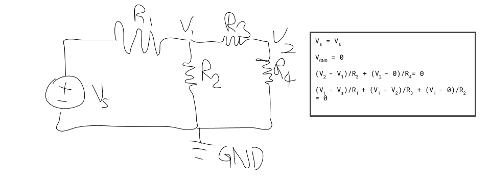
Note that this system can also be solved by the matrix equation
$$ \begin{bmatrix}
1 & 0 & 0 & 0 \\
-1/R_1 & 1/R_1 + 1/R_3 + 1/R_2 & -1/R_3 & -1/R_2 \\
0 & -1/R_3 & 1/R_3 + 1/R_4 & -1/R_4 \\
0 & 0 & 0 & 1 \\
\end{bmatrix} \begin{bmatrix} V_s \\ V_1 \\ V_2 \\ V_{\text{GND}} \end{bmatrix} = \begin{bmatrix} V_s \\ 0 \\ 0 \\ 0 \end{bmatrix} $$
There’s a bit of abuse of notation here with \( V_s \) referring both to the variable corresponding to the voltage level at the voltage source, and the value of the voltage it adds.
When we consider a circuit with only resistors, the current leaving the node from each branch is equal to the voltage drop along the resistor divided by its resistance. (Ohm’s Law states that \(V = IR\)). Thus, if \(N(i)\) refers to the set of nodes that are adjacent to node \(i\), we have
$$ \text{Current leaving node $i$} = \sum_{j \in N(i)} \frac{V_i - V_j}{R_{i,j}} = 0$$
At this point I practiced with a couple of circuits, calculating the voltage level at each node by hand, eventually moving onto just solving for the voltage level at each point by solving a linear system via matrices. After a couple of these I started to notice that all of this started to look a little familiar. That’s right—this looks a lot like a “graph kind of computation” would fit perfectly. The “nodes” in the circuit are just the same as “nodes” in a graph, and the resistors are just like a graph’s edges, storing information. Given the properties of circuits, I determined that the best thing to work with here are undirected graphs, with the possibility of having multiple edges between any two nodes; this is certainly possible in a circuit.
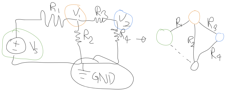
It turns out that that’s almost enough to start implementing a circuit simulator! You take your graph representation of your circuit, and run it through some function that will generate a linear system for that graph. Once you have that you can automatically solve the linear system to find the voltages at every single node. It’s still pretty early so I currently support circuits that have exactly one voltage source and where the only type of circuit component is a resistor.
I chose Julia to implement it, mostly because its matrix solving syntax is nice.
Here’s my circuit representation. A Node (which I’ve left out the implementation of) can either be a VoltageSource (adding a set amount of voltage) or a BaseNode, which is just a wire junction.
mutable struct Circuit
    ground::Node
    nodes::Dict{String, Node}
    edges::Array{Edge}

    function Circuit()
        ground = BaseNode()
        nodes = Dict()
        get!(nodes, "GND", ground)
        edges = []
        return new(ground, nodes, edges)
    end
end
And here’s my current version of solve_voltages. To generate the linear system I follow a couple of basic rules:
- If there are \( n \) nodes, then the linear system is a \(n \times n \) matrix \( S \in \mathbb{R}^{n \times n} \).
- To solve for the voltages, we solve for \( v \) in \( Sv = b \), where \( v, b \in \mathbb{R}^{n} \).
- The voltage level of any
VoltageSourceis just equal to the amount of voltage \(V\) it adds. This is actually strictly incorrect, but it works if there’s precisely one voltage source in the whole circuit. This is equivalent to setting \( S_{ii} = 1 \) and \( b_i = V \) if node \( i \) is our voltage source. - Similarly, the voltage level for the Ground node is always \( 0 \).
- If node \( i \) is not a voltage source: according to the formula referenced earlier, if a resistor connects node \( i \) to node \( j \), then add \( \frac{1}{R_{i,j}} \) to \(S_{ii}\) and subtract \( \frac{1}{R_{i,j}} \) from \( S_{ij} \).
using LinearAlgebra

# ...

function update_soln_matx!(S::Array{T, 2}, c, i, j, node1, node2, R) where {T <: Real}
    if !isa(node1, VoltageSource) && node1 != c.ground
        S[i, i] += 1 / R
        S[i, j] += -1 / R
    end
end

function solve_voltages(c::Circuit)
    names = [n[1] for n in collect(c.nodes)]
    node_to_idx = Dict([name => i for (i, name) in enumerate(names)])
    N = length(c.nodes)
    S = zeros(N, N)
    b = zeros(N, 1)

    z = node_to_idx["GND"]
    S[z,z] = 1

    for (name, node) in c.nodes
        if node isa VoltageSource
            i = node_to_idx[name]
            S[i, i] = 1
            b[i] = node.added_voltage
        end
    end

    for (name1, name2, con) in c.edges
        node1 = c.nodes[name1]
        node2 = c.nodes[name2]
        i = node_to_idx[name1]
        j = node_to_idx[name2]
        if con isa Resistor
            R = con.resistance
            update_soln_matx!(S, c, i, j, node1, node2, R)
            update_soln_matx!(S, c, j, i, node2, node1, R)
        else
            throw(MethodError("Only resistors supported at this time."))
        end
    end

    if DEBUG
        println(S)
        println(b)
    end
    return inv(S) * b
end
Here’s a couple of examples:
# Really basic case with two resistors.
c = Circuit()
register_node!(c, "n1", VoltageSource(5.0))
register_node!(c, "n2", BaseNode())
connect_nodes!(c, "n1", "n2", Resistor(5.0))
connect_nodes!(c, "n2", "GND", Resistor(10.0))
println(solve_voltages(c))
# output: [5; 3.3333; 0]

# This one is equivalent to the diagram at the top of the post with some
# arbitrary values chosen for resistances.
c2 = Circuit()
register_node!(c2, "n1", VoltageSource(12.0))
register_node!(c2, "n2", BaseNode())
register_node!(c2, "n3", BaseNode())
connect_nodes!(c2, "n1", "n2", Resistor(4000.))
connect_nodes!(c2, "n2", "n3", Resistor(2000.))
connect_nodes!(c2, "n2", "GND", Resistor(1000.))
connect_nodes!(c2, "n3", "GND", Resistor(2000.))
println(solve_voltages(c2))
#output: [12; 2.0; 1.0; 0]
So that’s where I’m at so far! There are some pretty natural extensions to what I’ve done so far:
- To support multiple voltage sources, I can leverage the superposition principle of circuits: in a circuit with multiple voltage sources, the voltage levels of each node is equal to the sum of what its voltage level would have been if each individual voltage source were the only one. This means I’d be needing to solve \( O(n) \) matrices for a total computational complexity of \( O(n^4) \), correct me if I’m wrong; this makes me think there’s some faster way to do this simulation.
- To suppport more kinds of circuit components, linear systems of real numbers won’t be enough to cut it. To support capacitors and inductors, I’d either need to start supporting complex-valued impedance or start using differential equation solvers. I have a feeling that if I want to support (ideal) op-amps before supporting capacitors and inductors I could get away with solving a linear program.
If you’re interested in learning more about circuit analysis, the book I’ve been going through is Electric Circuits by James S. Kang. It offers a really concise introduction to circuit analysis and has tons of exercises to practice with.